
SUSPENSION PHILOSOPHY


Suspension Philosophy
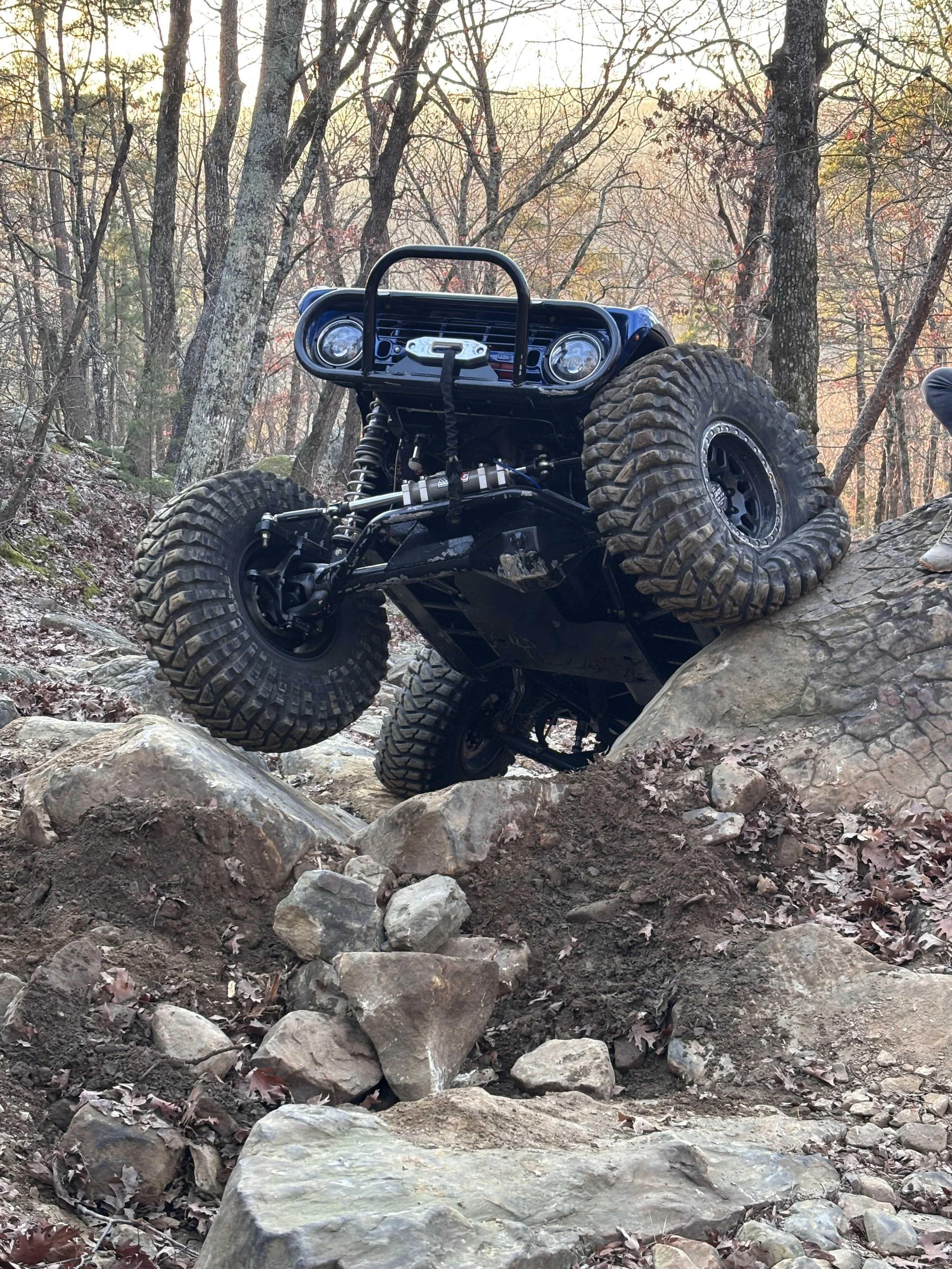
The suspension system was designed around three primary goals:
- Maximum traction and predictability while rock crawling
- Reduced unsprung mass for improved ride quality and suspension response
- High-speed stability without compromising crawling capability
- Lower center of gravity while maintaining optimal ground clearance
The geometry, spring rates, damping, and component selection were all chosen to support those goals while maintaining long-term reliability and serviceability.
Unsprung Weight Reduction
Significant effort was placed on reducing unsprung mass while maintaining structural integrity
This was accomplished by running battleborn wheels, wilwood lightweight brake system, Ford 2005+ unit bearing conversion, and running spider tracks 1/4” wall axle housing on front and rear.


Unsprung Weight Reduction Concept
When you lighten your chassis, you end up using lighter-weight springs, which do not rebound as fast as heavier-rate springs. This reduced rebound rate does not allow for maximum suspension utilization.
We addressed this issue by focusing on reducing unsprung weight, which allows for better rebound characteristics when blasting through the desert.
- Approximately 276 lb reduction in the front
- Approximately 276 lb reduction in the rear
- Compared to the previous build configuration
Reducing unsprung weight improves:
- Suspension response
- Ride quality
- Tire control
- Rebound characteristics
- High-speed stability
UPPER & LOWER LINKS
STRENGTH. CLEARANCE. ARTICULATION.
Upper & Lower Link Design
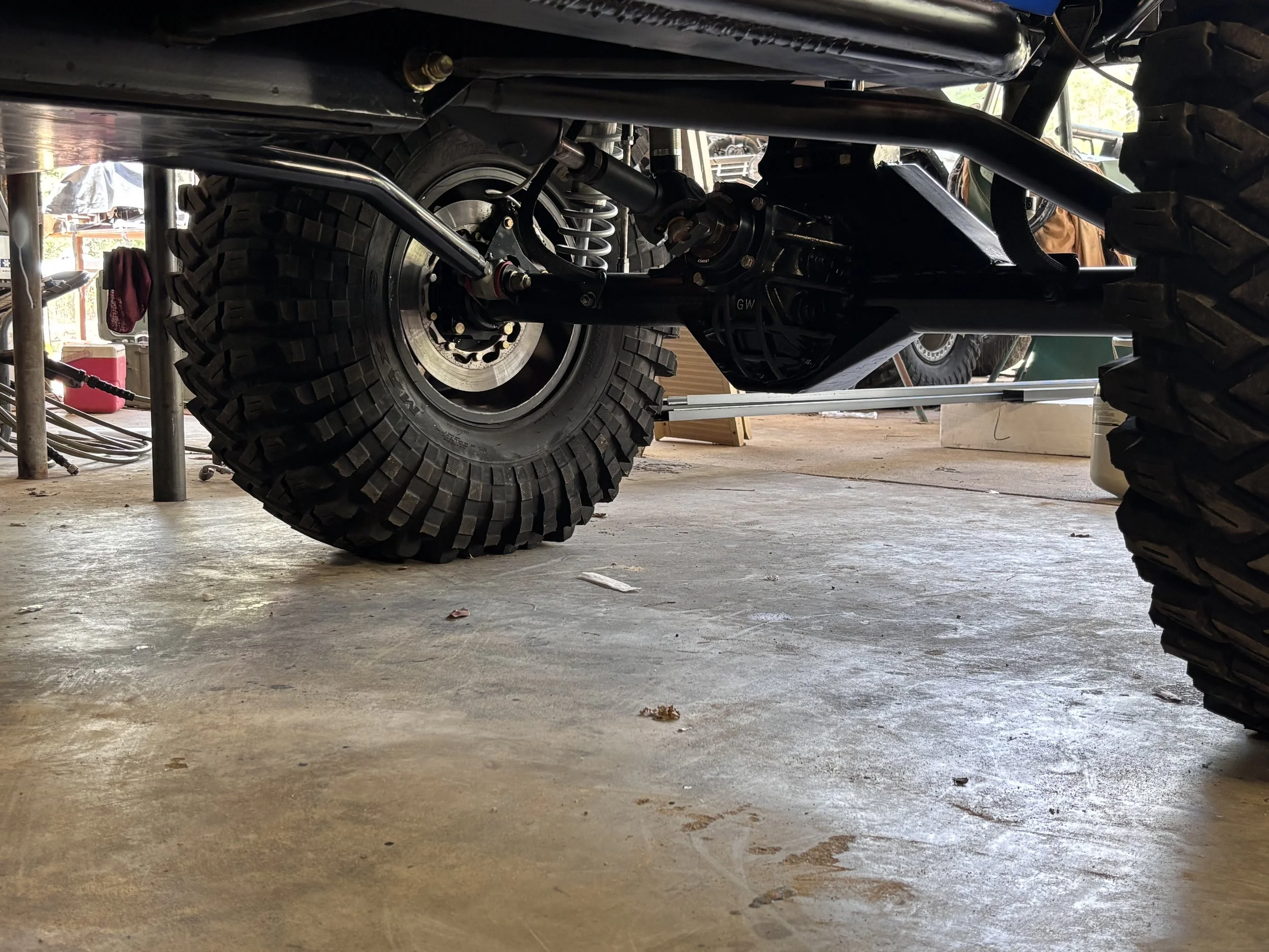
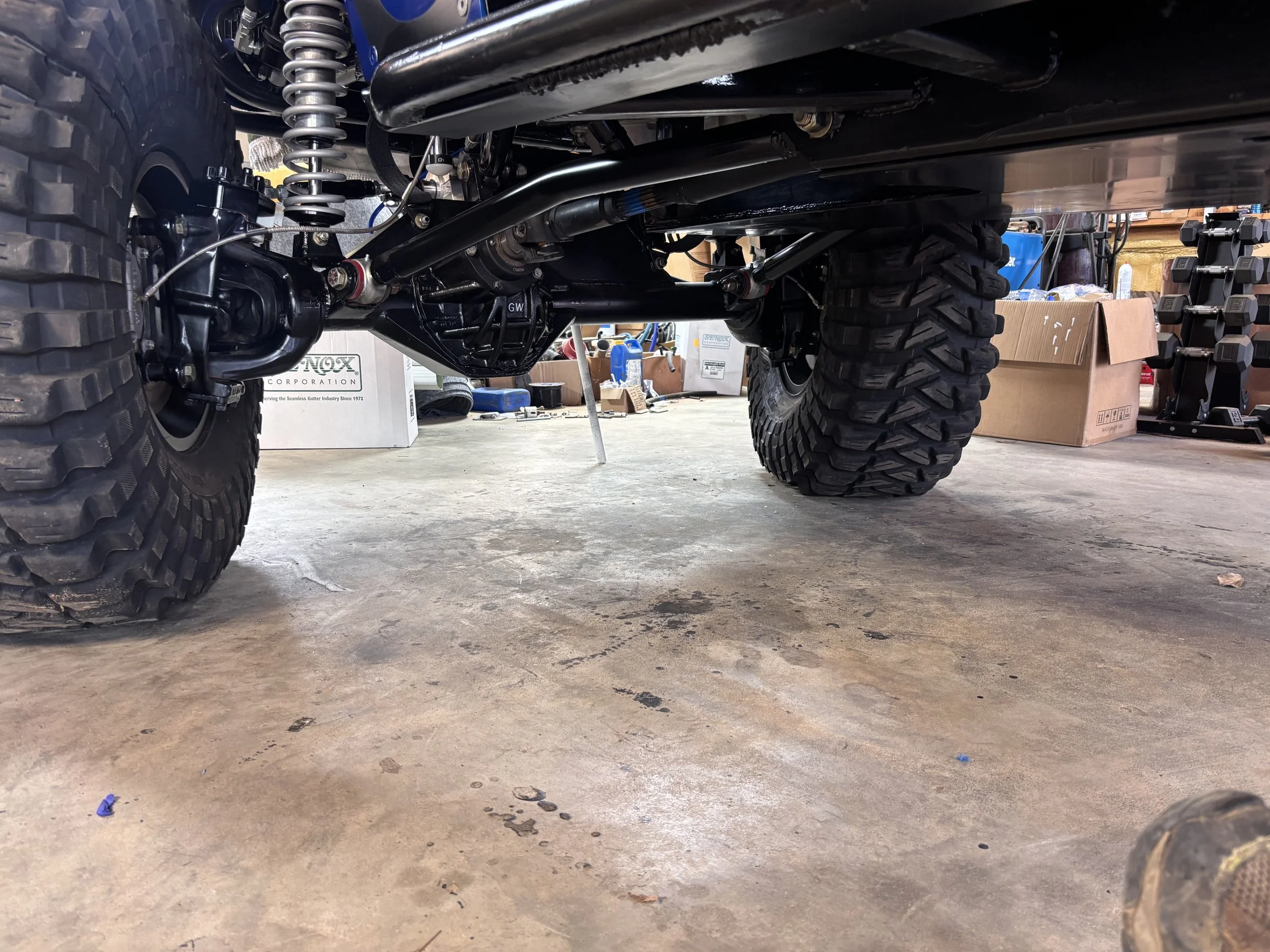
- 2-inch DOM tubing with 1/4-inch wall thickness
- Bent lower-link design for increased ground clearance and additional tire clearance while steering
- Ballistic Fabrication joints at the axle side
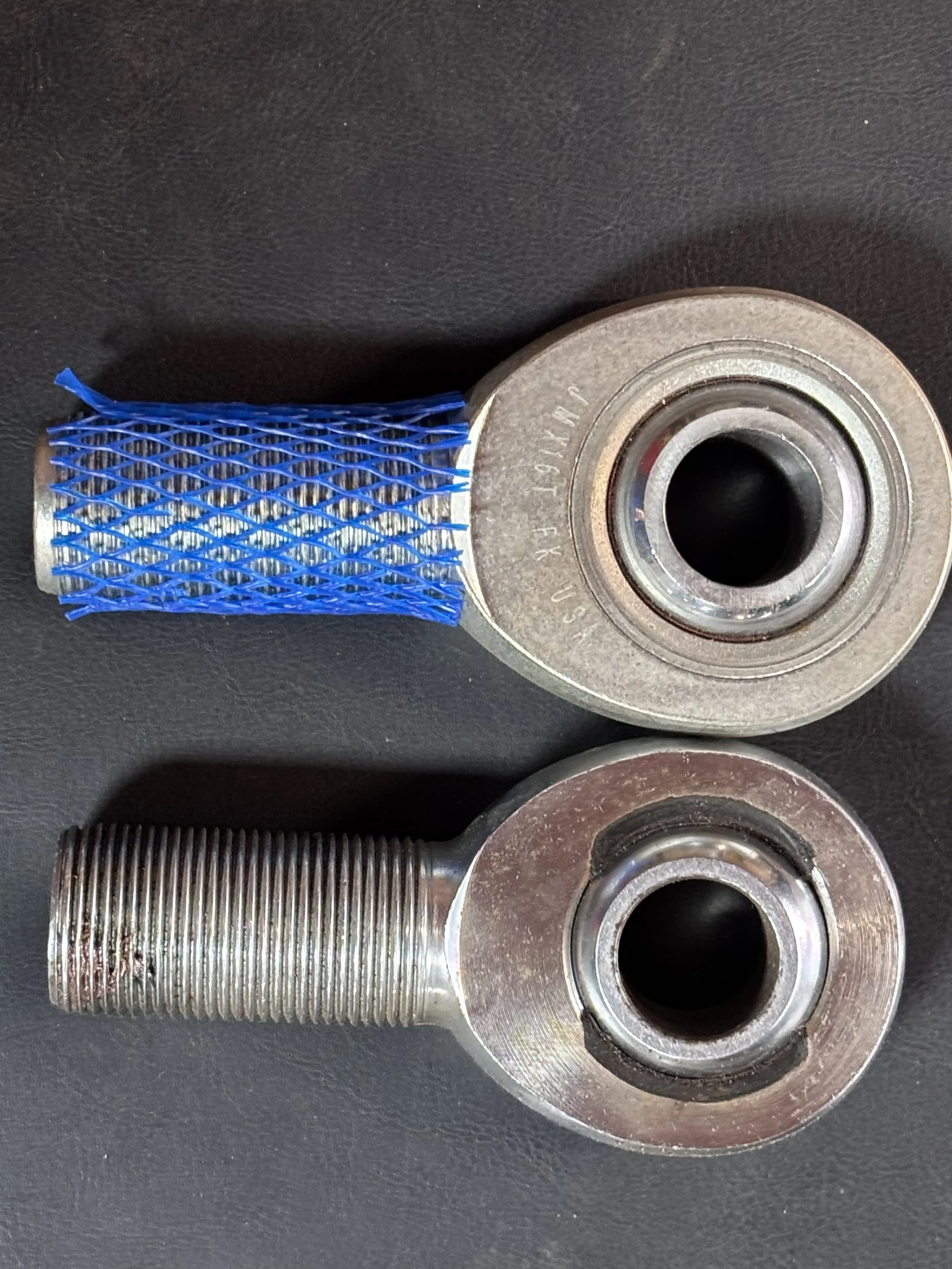
- FK heims are used throughout, including the steering heims
- Upper links are adjustable at the chassis side, allowing for tunable anti-squat and anti-dive geometry
The lower links were designed to maximize durability, suspension travel, and obstacle clearance while maintaining precise axle control in demanding off-road conditions.
REAR SUSPENSION
ANTI-SQUAT GEOMETRY
Anti-Squat Geometry
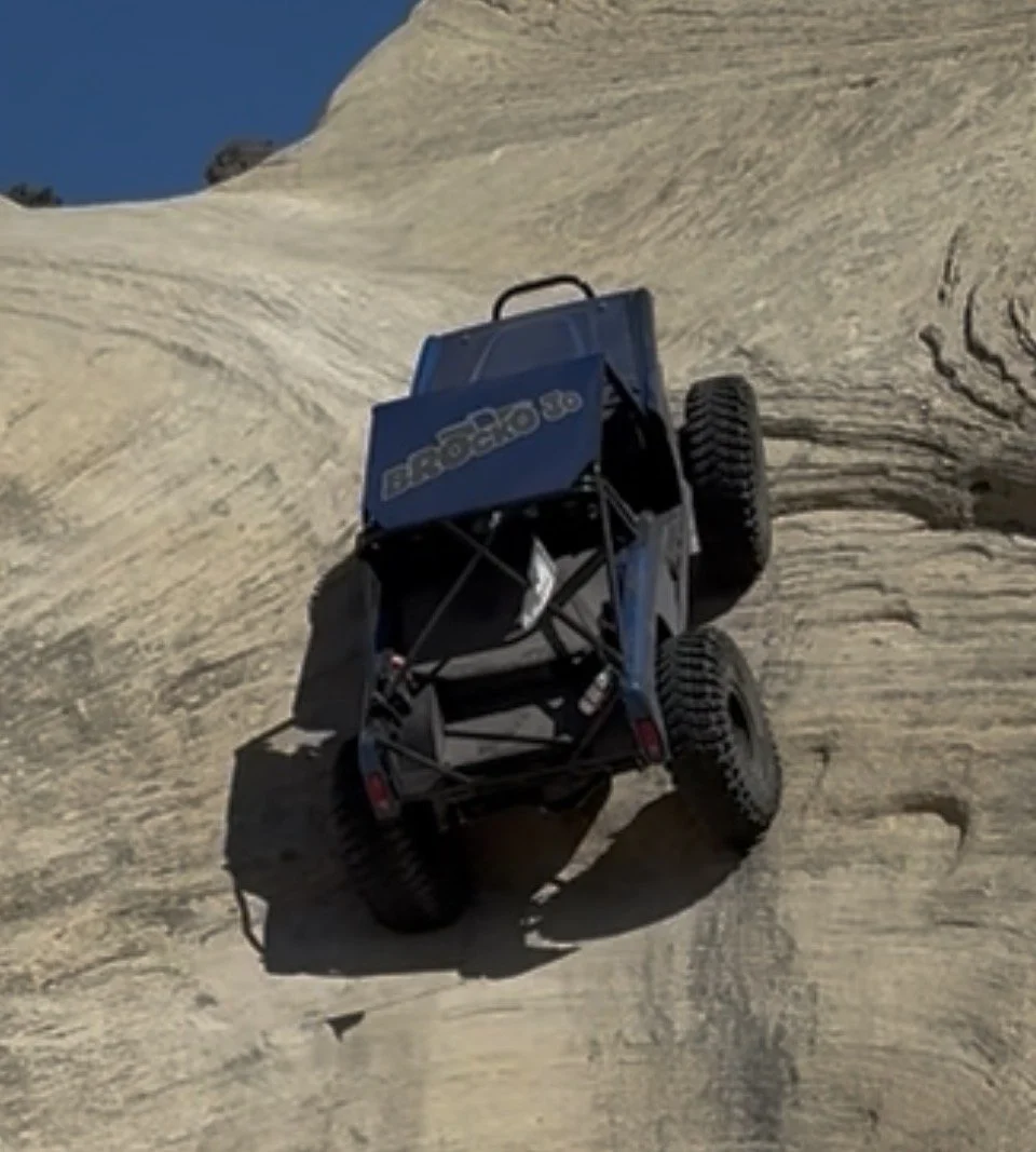
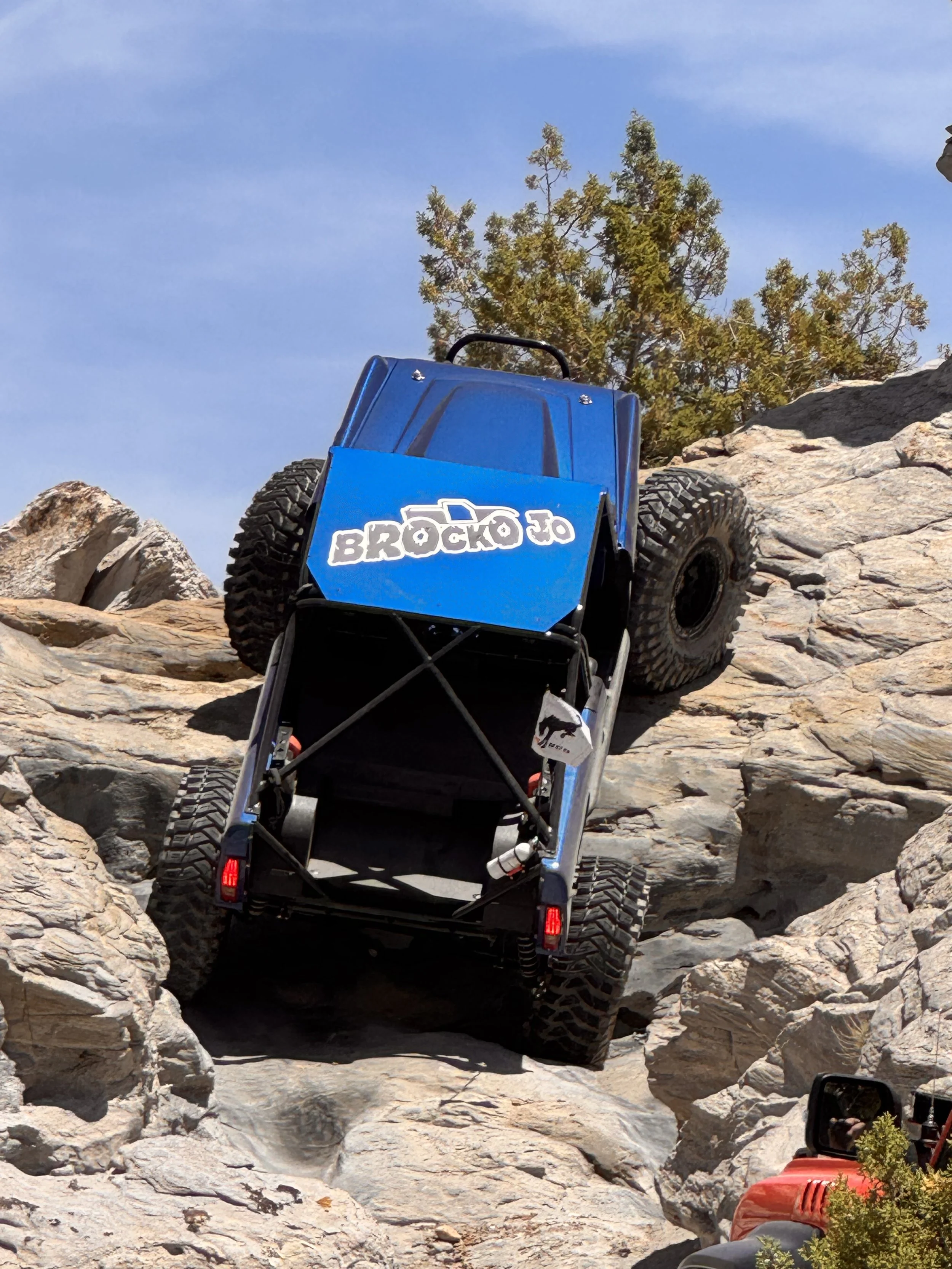
Suspension geometry was targeted near 100% anti-squat to optimize climbing performance and traction management.
Benefits include:
- Maintains forward drive on steep climbs
- Reduces hopping during traction loss
- Improves climbing predictability
- Keeps suspension loading more linear
The result is a rear suspension system that remains stable, predictable, and highly effective in technical climbing situations.
FRONT SUSPENSION
ANTI-DIVE GEOMETRY
Anti-Dive Geometry
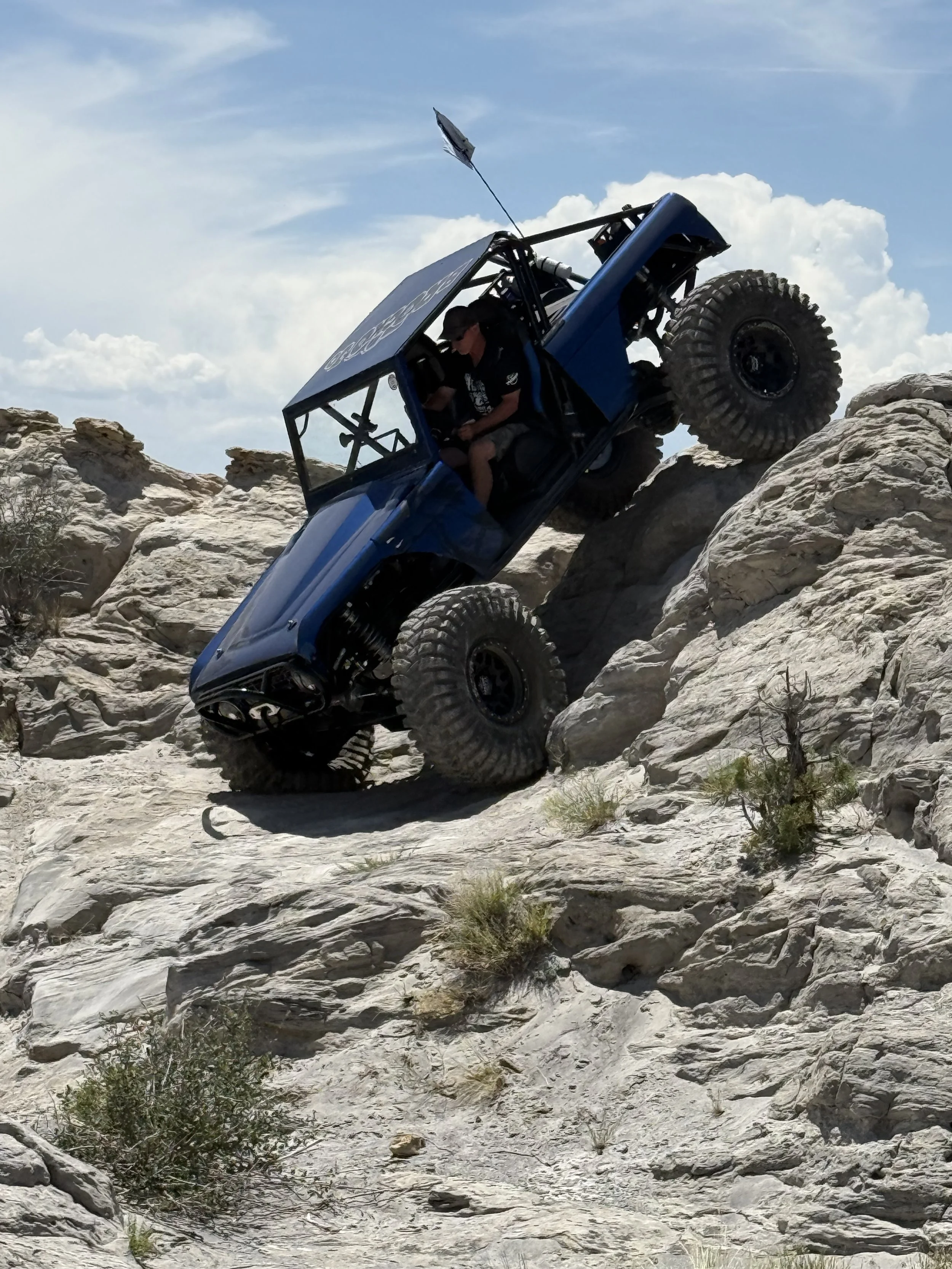
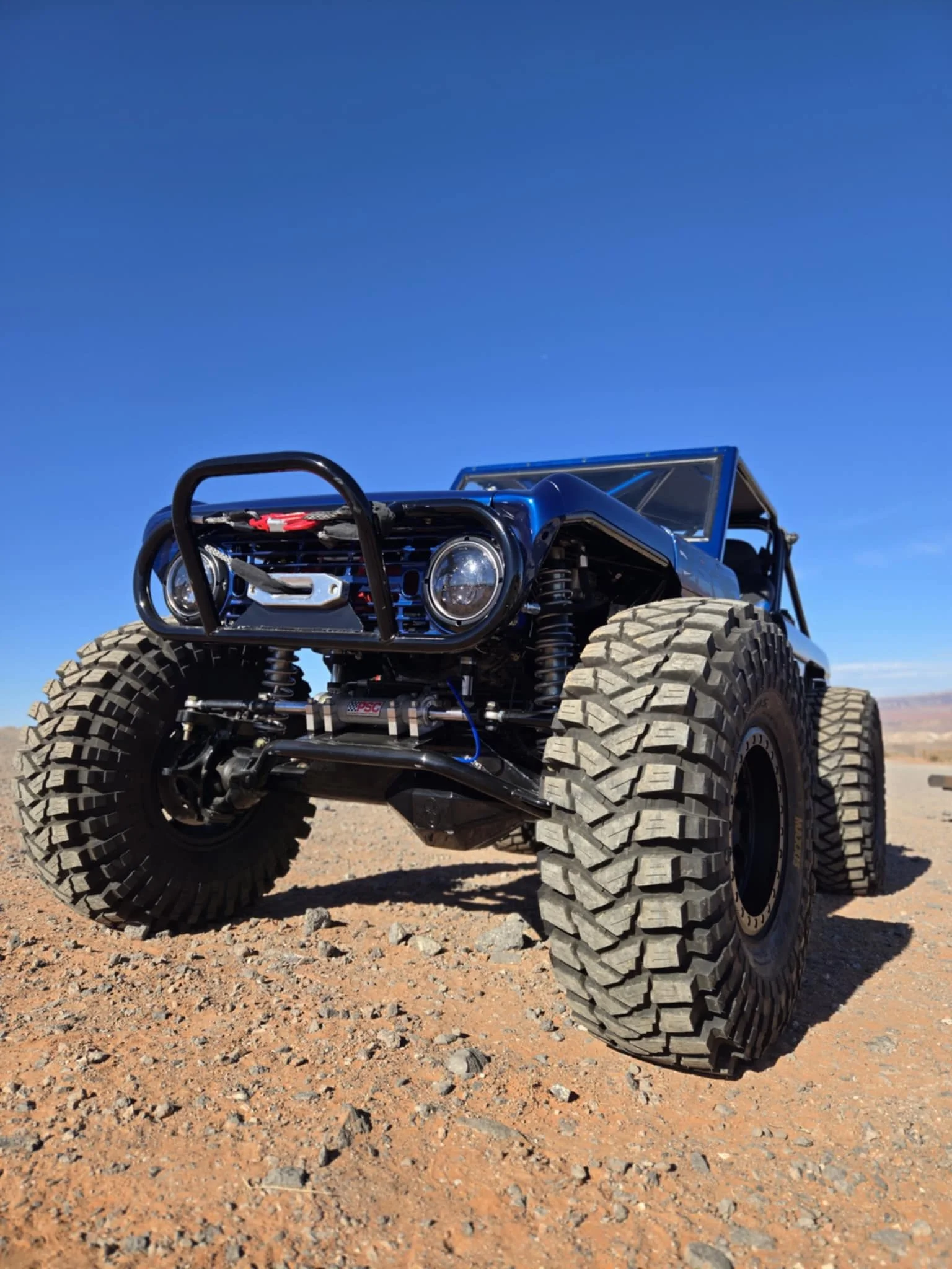
Front suspension geometry was targeted near 135% anti-dive to improve vehicle control during steep descents and obstacle transitions.
Benefits include:
- Improved chassis control
- Better stability during obstacle approach
- Increased predictability during aggressive crawling
This geometry helps keep the chassis composed during braking and steep descents while maintaining confidence and control in technical terrain.
SUSPENSION GEOMETRY DEVELOPMENT
Suspension Geometry Development
All suspension geometry was modeled and positioned during fabrication using the Triaged Suspension Calculator to optimize overall vehicle performance and tunability.
Key design considerations included:
- Link placement
- Roll center behavior
- Instant center positioning
- Anti-squat characteristics
- Anti-dive characteristics
Adjustable upper link brackets allow geometry changes for future tuning and terrain-specific setup adjustments.
SUSPENSION DIRECTS ACTIVE SYSTEM
ELECTRONIC SUSPENSION CONTROL
Electronic Suspension Control
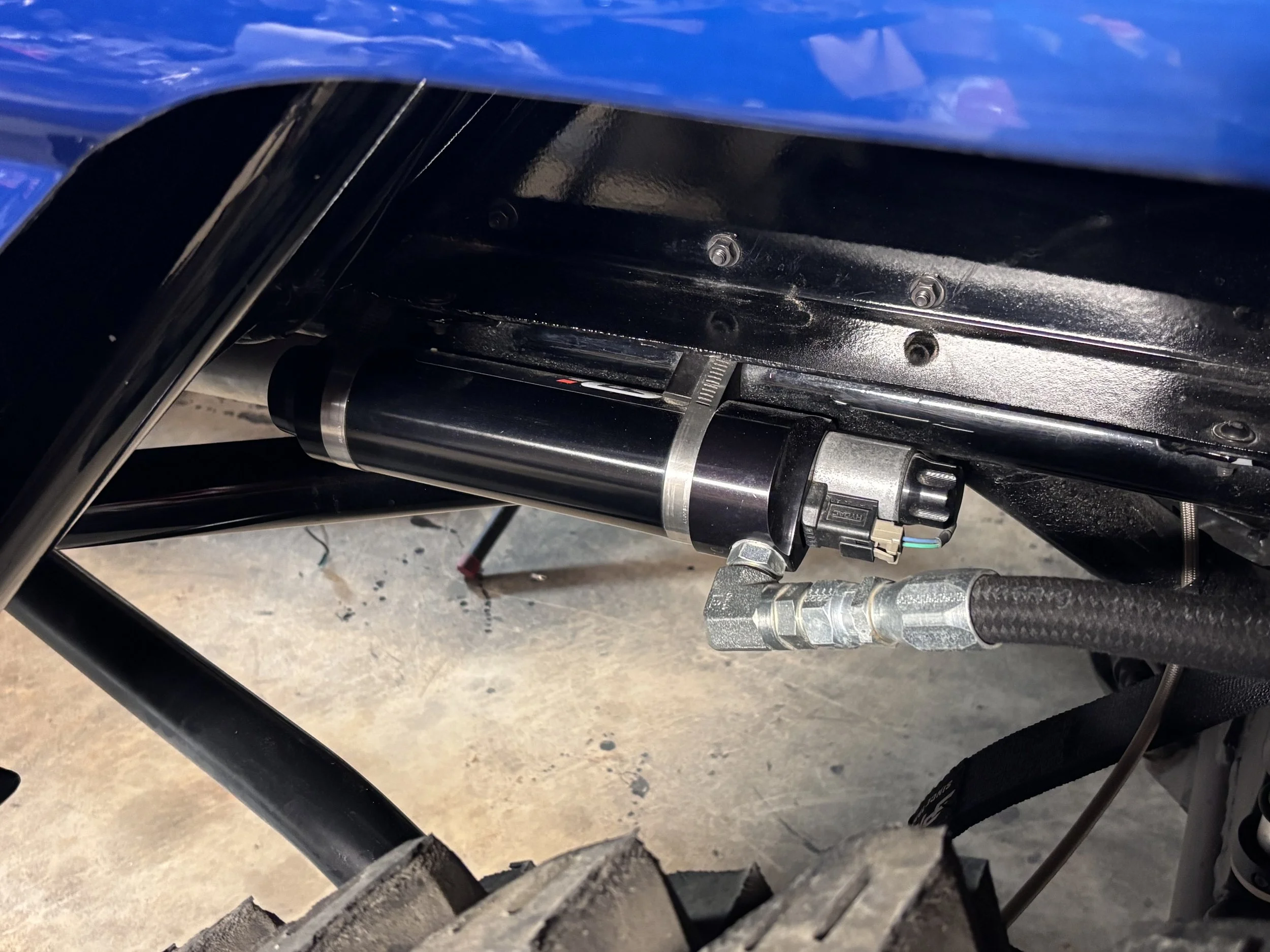
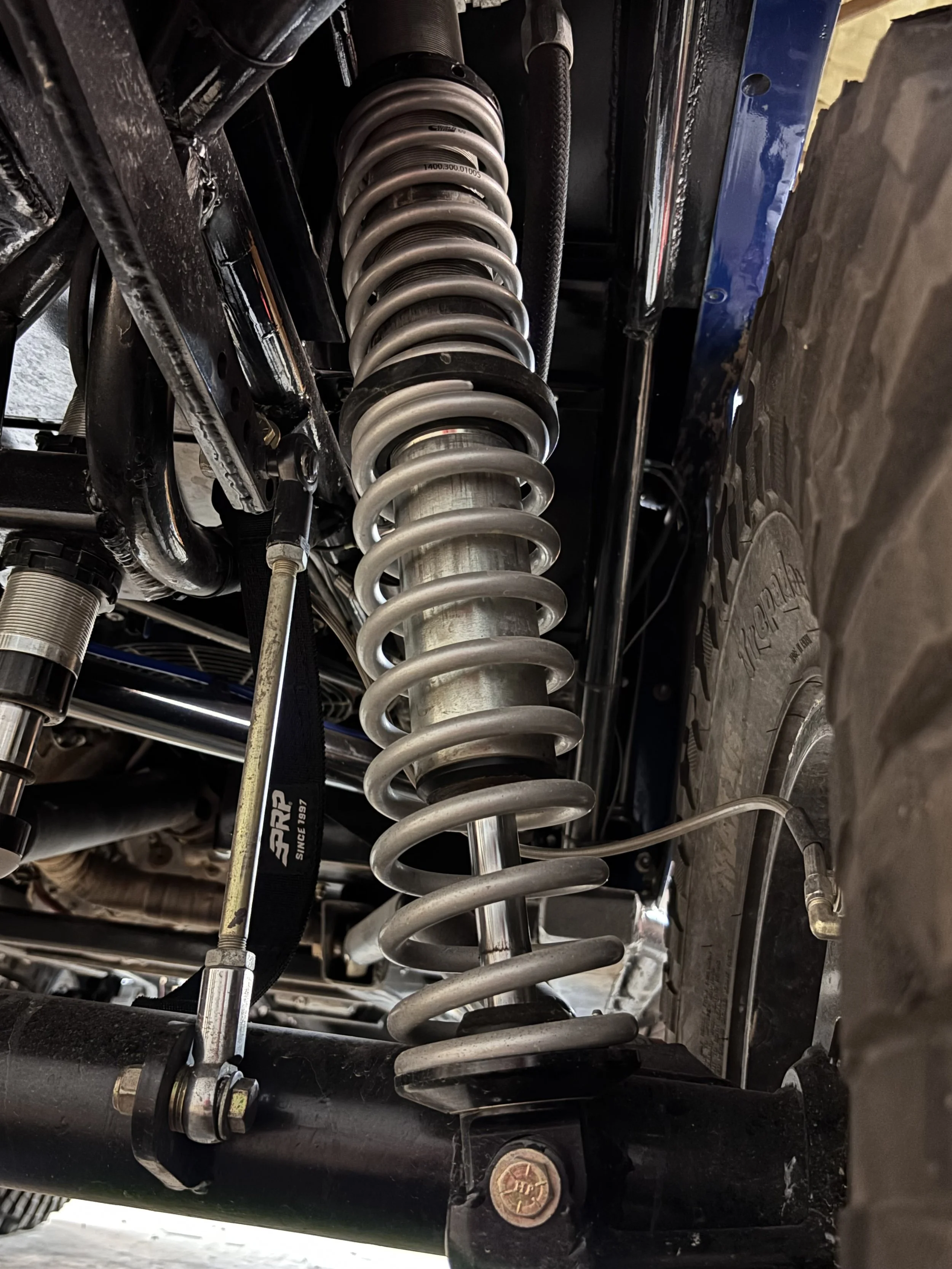
The suspension system incorporates quality Fox 2.5 coilover shocks provided by AccuTune and an integrated advanced electronic control package provided by Suspension Direct.
The system is designed to optimize ride quality, vehicle stability, suspension response, and traction.
System features include:
- Onboard computer control
- Real-time sensor monitoring
- Dynamic valving adjustments
- Approximately 500 adjustments per second
By constantly monitoring vehicle inputs and suspension movement, the system automatically adapts its damping characteristics to changing terrain and driving conditions.
Coilovers & Electronic Suspension Control
Fox 2.5 coilovers
Large-valve configuration
Tuned for both crawling and higher-speed terrain
While 2.0 coilovers are typically sufficient for rock crawling, 2.5 coilovers were selected for improved damping control during desert driving and higher-speed suspension events.
REAR SWAY BAR
ARTICULATION CONTROL STRATEGY
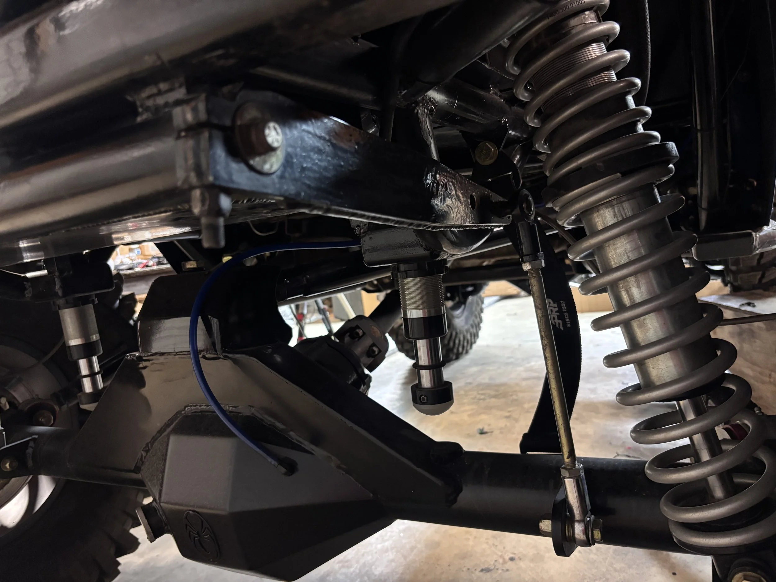
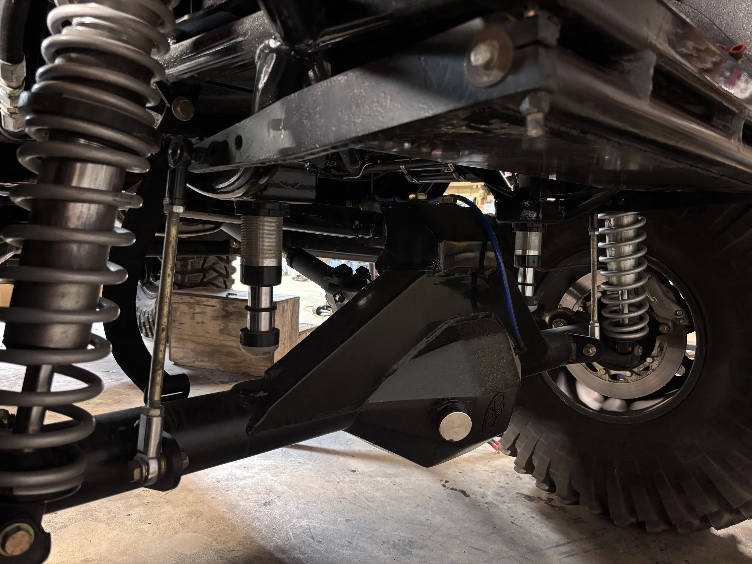
Rear Sway Bar Strategy
The rear sway bar was incorporated primarily to influence articulation behavior rather than traditional body roll control.
Design objectives included:
- Encouraging faster front articulation
- Improving stability during angled climbs
- Increasing predictability on vertical obstacles
This approach helps balance vehicle stability and suspension performance while maintaining excellent crawling characteristics in technical terrain.